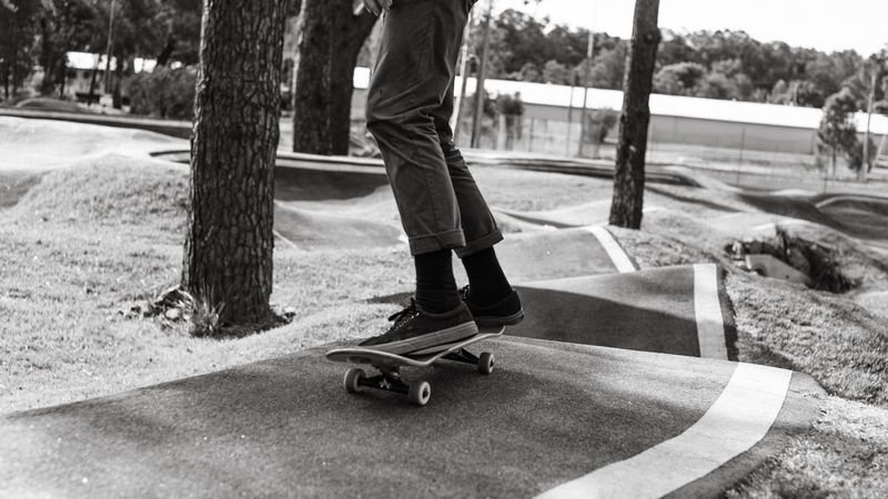
An electric skateboard at dusk is fast, silent and invisible, and the rider behind you has no way to know you are slowing down. This build puts an Arduino Uno (a small hobbyist microcontroller board), an accelerometer that senses motion on three axes, and a metre of individually addressable colour LEDs under a Boosted board: a sweeping light pattern for visibility, and a red brake light that comes on when the board measures itself slowing down, rather than when a switch is pressed. Source is on GitHub.
This post covers the parts and why each is there, the two cheap components that stop the Arduino rebooting itself, and the honest state of brake detection: it works in principle, and comparing one raw sensor reading against a threshold is not good enough on a real road.
The idea
Underglow answers “can drivers see me”. The brake light answers the harder question, “can the person behind me tell I am slowing down”. The accelerometer reads how quickly the board is slowing along its direction of travel; when that reading crosses a threshold, the rear LEDs go solid red. While accelerating or cruising, the strip runs a “Cylon” sweep, a single bright dot bouncing from one end of the strip to the other, driven by FastLED, an Arduino library for LED strips.
Parts, and the two that are not optional
| Part | Why it is there |
|---|---|
| Arduino Uno | Reads the accelerometer and drives the LEDs |
| 3-axis accelerometer, ±3 g range | Senses the board slowing down; “3 g” means it reads up to three times the pull of gravity |
| 1 metre of WS2812B LED strip, 30 LEDs | Each LED’s colour is set individually over one data wire |
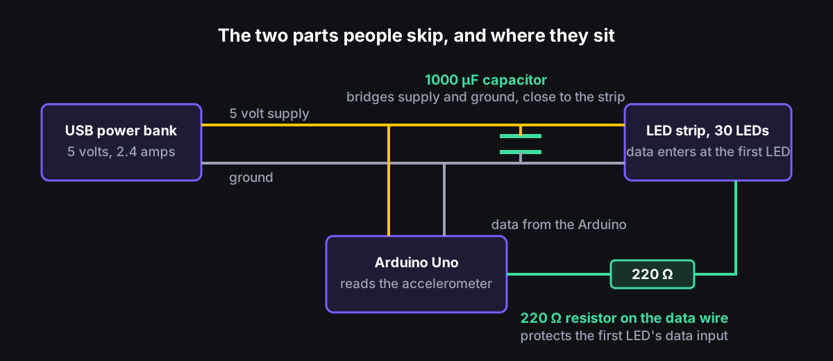
| 1000 µF capacitor across the 5 volt supply | Absorbs the surge of current when the strip first lights, so the Arduino’s supply does not sag |
| 220 Ω resistor on the data wire | Protects the first LED’s data input |
| Cygnett 5000 mAh USB power bank, 5 volts at 2.4 amps | Powers everything |
The capacitor and resistor are the two parts people skip. When the strip first lights it draws a sudden surge of current; without the capacitor across the supply, that surge pulls the voltage down far enough that the Arduino resets. The resistor protects the first LED’s data input. The figure shows where each sits.
What I expected and what the board did
I expected a single threshold on deceleration to separate braking from everything else. It does not. A hard push-off registers as “braking” unless the sensitivity is tuned carefully, and vibration from the road surface puts enough noise on the reading that comparing a single sample against the threshold fires when it should not. The mechanism is sound; the signal processing is not. The next iteration needs to smooth the reading first, with a low-pass filter or a short rolling average, before comparing it to the threshold. A better threshold on its own will not fix it.
The sweep and underglow work as designed.
Not yet done
The remaining items are physical: shrinking the electronics into the cable channel under the deck, sealing them against water so a puddle does not end the microcontroller, and confirming the power bank’s 2.4 amp output holds up with all 30 LEDs at full white. The power bank’s rating says it will; I have not measured it.
Why publish it anyway
Most hardware projects never leave the garage. This one is wired correctly, rides at night, and the FastLED patterns transfer to any longboard, e-scooter or bike. If you are building something similar, clone it and start from a rig that already boots.